BAJAJ PLAST

Plast Polymer Processing Aid
Overview
Overviewing
Polymer Processing Aid

Introduction
“Processing aid” is a general term that refers to several different classes of materials used to improve the processability and handling of high molecular weight polymers. The benefits are realized mainly in the melt state of the host polymer. Chapters 5 covers the subjects of lubricants and high polymeric processing aids based on waxes and mainly for PVC. The polymer processing aids discussed in this chapter are primarily fluoropolymer- or silicone-based and (they are also referred to as polymer processing additives). Their use is focused on polyolefin-based polymers. The most common/relevent example is the fluoroelastomer processing aid for eliminating melt fracture in LLDPE. Melt fracture can occur in all extrusion processes. There are a few options for eliminating melt fracture without processing aids, such as raising the melt temperature, widening the die gap, or changing the resin technology. But processing aids are more predictable and can be used effectively in most extrusion processes. Specific process information is provided in Section 6.6. As discussed in earlier chapters, it is essential to match specific processing aid chemistry to specific host polymers because of, in this case, the processing aid mechanisms of action.
Mechanisms of Processing Aid Action
Melt Fracture
How processing aids work is linked to the problems they are intended to solve. To develop a good description of the mode of action of a processing aid, it is necessary to review briefly various types of melt fracture and their origins. Although a good deal of debate still goes on about how some types of melt fracture start, there appear to be three categories of melt fracture:
1.Sharkskin (SS)
This surface defect is also called matte, orange peel, surface roughness, and surface melt fracture. One possible mechanism for the development of SS is elastic recovery from stored elastic energy at the die exit that tears the melt surface [1,2]. A second postulated mechanism is linked to a slip-stick phenomenon inside the die [3,4]. In both mechanisms, there is a critical shear stress (or critical shear rate), and the intensity of the fracture increases with shear stress (pressure) and shear rate (output).
2.Cyclic Melt Fracture (CMF)
In this case, an oscillation between stick and slip conditions at the die wall occurs. As the pressure increases in the extrusion die, the stress at the die wall exceeds the adhesive forces of the molten polymer to the metal. When this adhesion failure occurs, the drag forces on he melt are suddenly reduced and consequently, the output increases. The increase in output releases some of the pressure until the melt can stick to the metal die again. The pressure then starts to rise until adhesion failure. This process is repeated in a hysteresis loop until the extrusion conditions are changed.
3.Continuous or Gross Melt Fracture
This phenomenon usually occurs at much higher output rates and can be linked to several factors including resin architecture, entanglement density, die geometry and temperature.
Processing aids have significant effects on the two first types of melt fracture (SS and CMF), but only a small effect on the last one. Processing aids work by providing a release surface on the die wall that promotes the slippage of the molten polymer against the die wall. This slip surface prevents the storage of elastic energy inside the die by allowing it to release through a plug flow. It also prevents the molten polymer from sticking to the die, preventing slip-stick. Other benefits include reduction of die swell and elimination of die build-up.
Coating Mechanisms
Processing aids are usually added at levels between 0.01 and 0.1 %. Because they are largely immiscible with the host resin, they form a dispersed phase with a droplet size of about 1 micron. These droplets randomly reach the die wall, similarly to raindrops falling on a sidewalk. With time, the whole die is covered, providing a slip surface inside the die [5,4]. During the coating process, some portions of the die may be preferentially coated, resulting in partially melt-fractured extrudate. At the end of the coating process, melt fracture is completely eliminated. The back pressure in the extruder also gradually decreases to a minimum at the end of the coating process.
The polymer flowing through the die slowly abrades the process aid coating. Mineral additives such as pigments or antiblocks increase the abrasion. Therefore, there is equilibrium between the deposition and removal rate of the processing aid coating. Like any equilibrium, the process conditions can modify the coating and removal rates, and consequently, modify the level required to reach the equilibrium state where the die is fully coated. The time to reach equilibrium, or “conditioning time”, is also a concern.
Several factors have an impact on the equilibrium between deposition and removal of the processing aid. Concentration is the most obvious one. An increase in concentration increases the deposition rate and reduces the coating time. The quality of the processing aid dispersion also has a large impact on the coating rate. The finer the dispersion, the greater the probability is that a droplet reaches the die wall, resulting in a faster coating.
In a similar fashion, the throughput affects the coating time. The amount of processing aid reaching the die is directly proportional to the throughput [5].
The viscosity of the processing aid must also be matched to the base resin [6,7]. Most of the processing aids on the market are adequate for an LLDPE or LDPE with a melt index (MI) of 2 g/10 min. (2 MI) or lower and HDPE grades with fractional MIs.
The type and number of end-groups on the processing aid polymer is also reported to affect its performance. According to the literature, acidic (or functional) groups can react with the die sites (oxides and hydroxides) and promote adhesion. However, the literature is ambiguous on this topic, as some references claim an improvement with the presence of functional groups [8], while others claim a decrease in performance with increasing end group content [9].
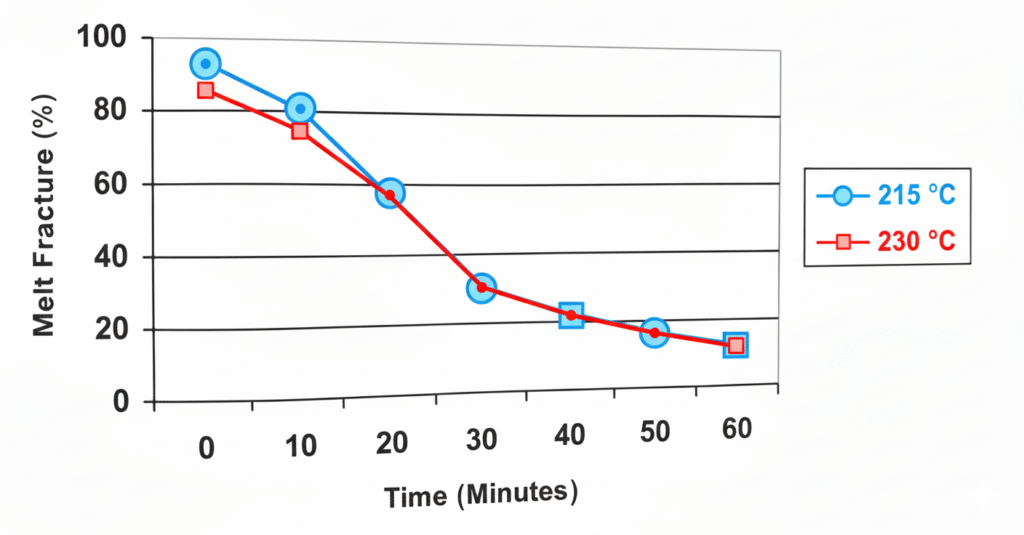
One of the factors affecting the efficiency of processing aids is the shear gradient in the flow channel of the die. At high shear stress, the flow profile in the die is sharp and leads to a higher gradient. The gradient efficiently pushes the processing aid toward the die surfaces. The processing aid coats more efficiently at higher shear rates (higher shear stresses). However, if the shear stress is high enough to induce CMF, the resulting pressure fluctuations can disturb the coating process. The optimum conditions, therefore, occur at the highest shear rate possible before CMF. This shear rate is temperature dependent and Fig. 6.1 shows the temperature may help increase the shear stress to its optimum. The shear rate for CMF was closer to the blown film process shear rate of 500s⁻¹.
Add Your Heading Text Here
Fig. 6.1 Lowering the melt temperature results in a faster rate of melt fracture elimination for a fluoropolymer processing aid. Extrusion was run closer to the LLDPE CMF shear rate CMF at 215 °C = 20s⁻¹ (CMF at 230 °C = 80s⁻¹). A process shear rate ~ 500s⁻¹ (0.3 MI, 0.46 LLDPE, 10% processing aid).
The importance of controlling the temperature is often overlooked. An example of this is given in Fig. 6.2, where the pressure reduction, as measured by capillary rheometry, is reported. At high temperature (250 °C), the stress is too low, while at low temperatures (150 to 170 °C), the stress is too high. The optimum temperature depends on the output, the equipment, and the resin.
Furthermore, even at constant shear stress, efficiency is slightly affected by temperature. As an example, in the case presented in Fig. 6.3, the temperature may improve or worsen the efficiency of the processing aid. This is most likely an adhesion/abrasion effect, as the processing aid is more able to withstand the stress from the flowing polymer.
Temperature °C
Fig. 6.2 Pressure reduction for a 1 MI LLDPE with 0.1% fluoropolymer at 400 s⁻¹ (0.5 mm diameter, L/D = 40)
Temperature °C
Fig. 6.3 Pressure reduction for a 1MI ml. LLDPE with 0.1% fluoroelastomer processing aid in the onset of CMF (0.5 mm diameter, L/D = 30)
Processing Aid Technologies and Historical Perspective
Original Technology
Probably the oldest and most subtle form of polymer processing aid is the low molecular weight component of a polymer’s molecular weight distribution. The better this low molecular weight “tail” was realized after developments in catalyst technology led to the commercial synthesis of relatively narrow molecular weight PE and PP. When the low molecular weight material was removed, the processability of the polymer suffered in some applications. This gave rise to the idea of using low molecular weight polyolefin as a lubricating additive.
Another archetypal processing aid technology was the use of metal stearates and fatty acid derivatives to reduce apparent viscosity in the polymer melt. These materials were usually added for other desirable properties, such as improving the flow of the materials to a solid state, reduction of extrusion hopper bridging, dye dissipation, and lowering the coefficient of frictional stability under conditions of long residence times on the heated metal die surface (see Section 6.2). This instability usually manifested itself as die build-up (also called die drool, die plate-out, and bearding). These lubricant additives are covered in more detail in Chapter 5.
Fluoropolymer-based Additives
Fluoropolymer-based process aids were first added to PE in the early 1960s [10]. At the time Du Pont Canada was developing new film resins in a pilot plant in Kingston, Ontario, for their film plant in Whitby, Ontario. The new resins exhibited sharkskin melt fracture. The R&D group worked on modifying the polymer to help alleviate the melt fracture. They made some modifications to the resin but before taking it back to the commercial enterprise in Whitby, they ran it first on a blown film line at the R&D facility in Wilmington, Delaware. The newly developed resin originally ran with no sharkskin melt fracture, however, a few hours later, melt fracture started appearing again. It was discovered that fluoropolymer had been run in the extruder just before the Du Pont trial. The trial did not completely succeed. The low level of fluoropolymer had been acting as a processing aid, preventing the sharkskin.
When Du Pont Canada first introduced LLDPE to the market, it contained fluoropolymer as a polymer processing additive. The processing aid was added to improve resin process- ability, enabling it to be extruded on LLDPE equipment at high speed and without exhibiting sharkskin melt fracture. When LLDPE was more widely introduced in the 1980s, resin manufacturers continued to add processing aid to match this competitive standard.
Blair first patented fluoropolymer to delay the formation of melt fracture at higher extrusion rates [11]. The patent mainly discusses the rate increases at which an article with good aesthetics can be obtained. The terminology used to describe this effect is “lubrication” with no theological data or references to apparent viscosity changes.
The fluoropolymer most widely used as a processing aid is a copolymer of vinylidene fluoride and hexafluoropropylene (1). This material is commonly referred to as “fluoroelastomer”, even though the polymer is not crosslinked when used as a processing aid and thus, has no elastomeric properties.
Add Your Heading Text Here
This polymer received FDA approval as an indirect food additive, when used in PE film, in 1988. It has been the primary fluoropolymer processing aid for the last 35 years and still is widely used today.
Much has been learned about the fluoropolymer processing aid mechanism in the years since its introduction. This understanding has led to improvements in fluoropolymer processing aid technology through blends with other polymers [12,13], formulations with other additives [14 to 18], and material forms. As the technology has evolved, the range of applications has widened to include many not attributable to a classical “lubricant”. This evolution has separated fluoropolymer processing aid completely from polymer lubrication technology.
Incorporation of Processing Aids
The function of a processing aid is directly affected by how well it is mixed in the host polymer. The processing aid must be present as relatively small particles that are well distributed throughout the host polymer. Recognizing that processing aids are used at relatively low levels (~0.1%), shear mixing techniques are utilized to incorporate the processing aid into the molten host polymer. A general guideline recognized in the industry is that discrete processing aid particles in the host polymer should be no greater than 2 microns in diameter.
Two primary techniques are used to incorporate processing aids into the polymers. Resin producers often include processing aid as a component of the PE additive package, already thoroughly incorporated during production. The second technique is for the fabricator to blend a processing aid concentrate into the host polymer. A detailed description of these incorporation techniques is available from processing aid additive suppliers [23-25]. Specific recommendations should be discussed directly with the processing aid material supplier and the mixing equipment manufacturer. Both techniques are effective and each method has specific advantages.
Direct addition during resin manufacture places the responsibility for processing aid incorporation on the resin producer. This method is widely used when high molecular weight extrusion grade resins, which have recognized processing difficulties or limitations, are produced. By handling the mixing, resin producers can offer an improved processing grade of resin, and their customers do not need to handle processing aid concentrates.
A disadvantage with this technique is that the resin producer establishes the processing aid level, which may be excessive for some fabricators and inadequate for others. Excessive levels generally do not present a problem for resin producers, but they generate additional costs for the resin producer. However, an inadequate processing aid concentration needs to be corrected, which most often means that the fabricator must add additional processing aid to the system by blending a concentrate into the host resin.
Adding processing aid concentrates gives fabricators greater flexibility. They are able to add processing aid to meet the specific requirements of their operations. Blending a process aid concentrate into all incoming host resins at specific levels minimizes processing concerns when changing resin grades, as well.
Applications for Processing Aids
There are currently five main areas where processing aids provide performance advantages. These are:
Melt fracture elimination and surface improvements
Die build-up reduction
Improved production capacities
Gel reduction
Improvements in processing recycled or reground resin
The primary end-use applications for processing aids involve LLDPE blown film, so in discussions of these five areas below, emphasis is placed on this application. However, blown film is not the only application area for processing aids. Other commercial applications include pipe, fiber, blow molding, injection molding, ram extrusion, and profile extrusion. Furthermore, LLDPE is not the only polymer where processing aids are used; this additive is also found in processing LDPE, HDPE, mLLDPE, PP, plastomers, thermoplastic elastomers, polystyrene, nylon, acrylics, PVC, and others.
Melt Fracture Elimination
Melt fracture elimination has historically been the primary benefit targeted by fluoropolymer processing aids, especially in high molecular weight polyolefin extrusion. For a typical LLDPE extrusion (1MI, LLDPE), a critical surface melt fracture occurs, when exiting the die, typically at a critical shear stress (see Section 6.2). Melt fracture and other distortions. Processing aids improve the physics surface roughness at a higher shear rate without melt fracture.
Figure 6.4 shows the typical response of LLDPE to 0.05% fluoropolymer processing aid, compared to an unaided control. The sigmoid curve is representative of the “conditioning time,” or the time it takes to develop an effective coating. The time to reach melt fracture elimination is a function of processing aid, this coating time is contingent on the die. Fig. 6.5 [6, 5] clearly shows this relationship. There is a superposition of melt fracture elimination curves between processing aid content and time. Although data for many commercial applications for melt fractured film, in most commercial film plants, producers have a high amount of melt fracture is not saleable. Therefore, conditioning time is important to the producers’ back-end production and to the customer. When you start with a melt fractured surface, the processing aid over the die surface reduces the conditioning time. Some users purge their extruders with a concentrate of processing aid and achieve a melt fracture elimination in as little as 5 to 10 minutes. Only a maintenance level of processing aid between 0.05 and 0.1% is required after pre-conditioning.
Add Your Heading Text Here
According to the processing aid mechanisms (Section 6.2), there are several factors related to the processing and the host polymer that affect the rate of processing aid dispersion and coating match. Other physical factors that affect the melt fracture elimination, such as the molding, processing aid are resin type, the resin melt temperature, shear stress, shear rate, processing equipment (Section 6.6), and interactions with other additives (see Section 6.10).
Add Your Heading Text Here
Die Build-up Reduction
The elimination of die build-up is another benefit of using a processing aid. Although it was not the initial application focus, it has been widely recognized from industrial evaluations and applications. Several references address this issue [26–29]. When discussing die build-up, it is important to recognize that deposits can present themselves on the outer surface where the polymer melt exits the die and also inside the die, on the channel wall.
Deposits at the die exit are usually characterized as low molecular weight components of the polymer, additives, and oxidative degradation products of both. If these deposits are allowed to grow, they can lead to processing problems and create die lines in the extrudate. They also tend to be randomly released, creating defects on extrudate surfaces. Fig. 6.6 shows the condition of a die exit, after extruding a pigmented PP control resin, compared to its condition after the same resin containing a processing aid additive was extruded.
Add Your Heading Text Here
Internal deposits are associated with stagnation and long residence times in the extruder. These deposits are similar to exterior build-up but because of the lack of oxygen in the extruder, they may exist as thermally degraded species. This creates a site for thermal degradation of the resin, ultimately resulting in crosslinked polymer gels [30, 31].
The processing aid eliminates die build up by providing a layer between the metal of the extruder and the polymer. As this coating forms, the processing and displaces degraded material clinging to the metal surface. The purging of black specs and other degraded material is frequently, but wrongly, interpreted as instability resulting from the processing aid. This purging process can take minutes up to hours, depending on the initial cleanliness of the extruder. The processing aid keeps the extrudate free of black specs and gels, along with the other benefits it provides.
When a fluoropolymer coating is established at the die exit, the exiting melt is less likely to swell over the die exit surface. As a result, external deposits are more likely to be carried away with the extrudate, eliminating build-up and its random release onto the extrudate surface.
Internal to the extrusion process, the processing aid establishes a slip velocity at the polymer/metal interface [54]. This minimizes stagnation in the extrusion process, which reduces the potential for the thermal degradation associated with long residence times.
Improved Production Capacity
Improved productivity can encompass increases in output, operating processing equipment more efficiently, reduction in equipment maintenance time, and other attributes of value to the specific processor. In general, the presence of the processing aid in itself does not improve productivity, but it rather improves the extrusion process and expands process capabilities. When using a processing aid, the resistance of the polymer melt to flow from the extrusion die is reduced. As a result, die pressure and extrusion drive motor torque go down. These reductions can be measured to assess improvements in productivity.
Fig. 6.7 displays measured die pressures that occur during the extrusion of a series of LLDPE/LLDPE resin blends, with and without a processing aid. Comparisons are made at the same output and processing temperature. A 10 to 18 % reduction in extrusion pressure is observed after adding processing aid to either the blends or 100 % LLDPE.
To quantify productivity improvements, comparisons are made between extrusion processes operating with and without a processing aid present. If this is done at equivalent process temperatures and extrusion outputs, a reduction in extrusion motor energy consumption can be observed. If comparisons are made at equivalent process temperatures and extrusion pressures, increases in extrusion outputs are observed [32–34].
Fig. 6.8 displays the energy consumption during extrusion of a 0.9 MI LLDPE resin with and without a processing aid. Both extrusions occur at the same output and processing temperature. A 60% reduction in energy requirements is observed after adding fluoropolymer processing aid.
Fig. 6.7 displays the reduction in extrusion pressure after adding fluoropolymer processing aid to a series of LLDPE/LLDPE resin blends.
Fig. 6.8 displays the reduction in extrusion energy after adding fluoropolymer processing aid (0.9 MI LLDPE).
Fig. 6.9 displays the output when a 0.9 MI LLDPE resin is extruded with and without a fluoropolymer processing aid. The extrusion pressure and processing temperature remain constant. An 83% increase in output is observed after adding the processing aid and increasing the extrusion rpm.
Productivity improvements can also relate to reductions in maintenance time. A processing aid attribute noted earlier in this chapter is the ability of these materials to eliminate die
Fig. 6.9 displays the increase in output after adding fluoropolymer processing aid (0.9 MI LLDPE).
build-up during extrusion. Eliminating die build up also eliminates the need to periodically stop equipment to remove these deposits. Industrial observations have also confirmed reductions in the time to complete color or resin changes, probably resulting from the processing aid minimizing material stagnation in the extrusion process.
Gel Reduction
Recent studies [30, 31] have shown that processing aids can help reduce crosslinked, oxidized, and unmelted/unmixed gels [55] which may form in the extruder. It is believed that this mechanism is similar to that of die build up elimination (Section 6.5.2). The processing aid coats the metal surfaces inside the extruder, effectively changing the interfacial tension between the metal and molten polyolefin to that of metal to fluoropolymer to polyolefin. The low energy surface, provided by the fluoropolymer coating, prevents the accumulation of low molecular weight species and oxidized PE and reduces the tendency for polymer to “hang up” and degrade causing crosslinked and oxidized gels. Dose levels in the 0.01 to 0.03 % region are recommended although this may vary depending on the individual resin.
The mechanism for reducing unmelted/unmixed gels is thought to be related to the prevention of solid bed break-up in the feed section of the extruder. Solid bed break-up can lead to poor mixing and the passing of unmelted particles all the way through the extruder. Fluoropolymer processing aid may prevent premature melting in the feed section, helping to maintain a coherent solid bed. These types of gels are more common with lower melting, low density polyolefin plastomers (e.g., metallocene-catalyzed LLDPE).
Recycled Plastics
The post consumer recycling of plastics can involve complex processing problems, because of the commingling of different polymers or the same polymer with vastly different densities or molecular weights. Processing aids have already been shown to reduce the extruder pressure of virgin blends of LLDPE and LDPE (Fig. 6.7). Another common blend of polymers resulting from the recycle process is LDPE and HDPE (bags and milk jugs). Fig. 6.10 [35] shows significant pressure reduction and delay for the onset.
Fig. 6.10 displays the reduction of pressure for a 50/50 LDPE/HMW-HDPE blend in a capillary rheometer; data obtained until the onset of melt fracture (LDPE = 2 MI, HDPE = 2 HLMI, 190°C, 0.5 mm flat entry die, L/D = 40/1).
of melt fracture for a 50/50 blend of LDPE and HDPE extruded in a capillary rheometer. increase of extrusion pressure does not solve the incompatibility issue, but it can increase the flexibility fabricators have for generating an article of reasonable quality
Effects and Advantages in Different Processes
Blown and Cast Film
Blown and cast films are the two largest application areas for fluoropolymer processing aid and a large percentage of commercially available LLDPE below 2 MI contains processing aid. The benefits from the use of a processing aid in these films relate to the advantages to using a processing aid film besides the benefits discussed in Sections 6.5.3 to 6.5.5.
Running an LLDPE on narrow die gaps can improve impact strength because draw down is reduced, but may provide poor clarity. Using wider gaps, this problem can be avoided or reduced, but may provide poor clarity with narrow die gaps [36]. But, unlike blending problem into an LLDPE, the improvement does not come at the expense of other physical properties such as tensile strength. Processing aid can also improve the impact property balance, machine vs. cross direction, by reducing the stress and elongation of the polymer chains in the flow direction.
The addition of polymer processing additive has been shown to improve the cast/ or cast film processor has over film thickness. Shown in Fig. 6.11 are results of a thickness histogram for a film processor. Data collection from the same period of time. The formulation containing processing additive has a much narrower distribution of gauge and the data is centered on the desired thickness (11.25 mils).
With PPA
Without PPA
Histograms comparing 0.06% polymer processing aid (PPA) films, with and without
The question of the effect of processing aid on physical properties is often raised. Studies have shown that fluoropolymer based processing aids do not migrate. The properties related solid state and would not be expected to have any negative effects on physical aids are somewhat to the film surface [32, 56, 57]. Somehow the liquid phase after the host polymer has cooled more mobile because they tend towards the liquid phase to room temperature. This can cause print adhesion problems. Other silicone processing aid products have been designed to improve printing and adhesion properties [21].
Pipe and Tubing Extrusion
Processing aid can be used in pipe and tubing extrusion to lower the apparent viscosity of the resin [37], to eliminate die build-up [26-28], or to give a smoother, glossier surface. Processing aid has been used successfully in HMW-HDPE and PP for these applications. At normal processing aid concentrations, no detrimental effects have been seen in physical properties such as long-term hydrostatic strength (LTHS or “hoop stress”) and burst strength [61].
Fiber and slit tape extrusion
PP and PE fiber and slit tape processes can benefit from the addition of processing aid in a number of ways. Because processing aid reduces the apparent viscosity of the resin, fiber producers can process higher molecular weight materials under conditions similar to lower molecular weight materials, and receive physical property benefits such as higher strength, less fiber breakage, and less die swell. With the addition of processing aid, metallocene PP melt blown fiber has been produced from a relatively low melt flow rate (15 MFR) resin with a smaller fiber diameter than normal (Table 6.1) [29]. Less die swell contributes to the smaller diameter, which can create a better filter substrate.
| No Process Aid | PPA (0.05 %) | |
|---|---|---|
|
Fiber Diameter (μm) |
17.8 |
12.1 |
Other, more subtle benefits for fiber extrusion have been seen in various fiber processes. Because processing aid coats the metal surfaces of the extruder and die, it prevents the build-up or stagnation of pigments. This can decrease the time needed to transition from dark pigment to light pigment in fiber production. In slit tape or baffle, processing aid has helped reduce surface roughness, enabling bags woven from this material to be stacked without their sliding off. Processing aid helps extruders stay clean by virtue of the non-stick coating created at the polymer/metal interface. Because much of the material that coats a screen pack or clogs a spinneret is carbonaceous extruder build-up, this coating can extend runs between screen pack changes, fiber breakage, or machine cleaning time.
Blow Molding
Fluoropolymers and other processing aids can be used in extrusion blow molding to eliminate melt fracture, increase gloss, and reduce extrusion temperatures for higher melt strength and better parison control. Fig. 6.12 [38] shows the effect of increasing processing aid concentration on the gloss of a pigmented HDPE.
Fig. 6.12 Gloss of blow molded HDPE bottle vs. processing aid level (0.5 MI, 0.95 g/cm³)
Injection molding
Silicone based processing aids can be used in injection molding to increase mold fill efficiency, reduce polymer melt temperature, improve mold release, reduce polymer coefficient of friction, and improve scratch and mar resistance [21]. Weld line strength for thermoplastic olefins can also be improved with ultra high molecular weight silicone polymers (UHMW), as shown in Fig. 6.13.
Fig. 6.13 Weld line strength of TPO with silicone based processing aid
Currently available fluoroelastomers are typically not used in injection molding applications because the shear rates are high enough to abrade the material off the sprue and other metal surfaces.
Processing Aid Use in Other Polymers
Thermoplastic Rubber (SEBS, SIS, EPDM, EPR)
Processing aids can be used in thermoplastic rubber extrusion to lower apparent viscosity [29]. Although today, the extrusion of these polymers is rarely done as the major phase, the trend is moving in this direction for adhesives and other applications. Some data suggests that the amount of styrene can limit the effectiveness of fluoropolymer processing aids [29] because of the solubility of the fluoropolymer in the styrenic phase.
Nylon
Fluoropolymer processing aid has been shown to reduce die build-up in nylon pipe extrusion [28]. Other attempts to use commercially available fluoropolymers in nylon have yielded discoloration resulting from an acid/base reaction with unreacted amine
Polyester
Fluoropolymer processing aid has been shown to increase draw ratio, lower processing temperatures and reduce die build-up in PET fiber processes [39].
How to Evaluate a Processing Aid
Capillary Rheometry
The capillary rheometer is used as a simplified extruder to determine if a specific resin compound responds to certain processing aids. Although it cannot determine the amount of additive that optimizes the resin’s performance (see Extrusion Trial, 6.8.2.1), to some extent it can demonstrate the efficiency of a processing aid and interference effects caused by other additives.
The equipment includes a heated barrel, test plunger, and capillary die, all of which should be cleaned before each use (each time the barrel is filled). Several equipment designs are available. The following discussion assumes a constant speed rheometer, equipped with a pressure cell to measure the piston load. A constant pressure rheometer or a pressure transducer may also be used, although the procedure may need to be modified. The efficiency of an additive is determined by the difference in shear stress (or pressure or viscosity) between the resin with and without processing aid under constant conditions. The pressure reduction (or percent reduction from the unaided sample) can also be measured. The conditions should reflect full-scale production conditions, keeping in mind that long residence time in the rheometer can cause polymer degradation, especially at high temperatures. In some cases, it may be necessary to use lower temperatures on the rheometer than on the production line.
Purging the Rheometer
It is a good practice to run a purge and a control sample of a well stabilized, unaided LLDPE (or of a standard resin) between each sample to be tested to verify the cleanliness of the equipment. Small amounts of processing aid or of degradation products on the die can significantly affect test results.
A purge compound consisting of 70% CaCO3 in LDPE can be used because CaCO3 scours the processing aid and any degradation products from the die wall and the barrel without damaging the die metal. A full barrel of the purge is pushed through the die at maximum speed (avoid pressure overload) before the control. The control resin is then placed in the barrel and the first half of the barrel is used to remove (at maximum speed, avoid pressure
overload) any purge compound that is not removed by the standard cleaning procedure. The second half of the barrel is used to record the control values.
Typically, two shear rates are used for the control: a low shear rate where the resin is not melt fractured, and a high shear rate, preferably the highest shear rate before cyclic melt fracture. The shear stress should always be within 3% of the running average. A lower value indicates contamination. A partially fractured strand at the higher rate also indicates contamination (observe under a microscope). In either case, the system should be further cleaned before testing a sample. A drift in the control value with time indicates gradual deterioration of the die (corrosion, scratches, and die lip damage).
Testing the Samples
Sample testing includes the testing of the polymer under investigation with and without processing aid. Testing the resin without processing aid first allows you to select a better test condition for the processing aid containing sample. The samples are usually tested over a range of shear rates in an increasing sequence. Typically, five to ten data points per decade are sufficient. The shear rate of the full-scale process should be included.
Once the data is collected for the resin without processing aid, the onset of SS and CMF are identified. The sample containing the processing aid is then tested. The die must be first fully coated before measuring the apparent shear stress of the resin. This is best accomplished by extruding the sample at the highest shear rate before CMF, as recorded with the resin without processing aid.
The coating of the die usually takes between ¼ barrel and a few barrels. The coating is complete when the pressure reaches a stable value after the slow pressure decrease caused by the processing aid coating the die (see Fig. 6.14). If more than one barrel is required for the coating of the die and the testing of the sample, the equipment should be cleaned between each barrel fill. However, to avoid disturbing the coating, the inside of the die should not be cleaned.
Fig. 6.14 Die coating reaches equilibrium as measured by pressure in a rheometer
The sample is then extruded through the same sequence of shear rates as the resin without processing aid. It is a common practice to collect a strand sample from each shear rate (for both samples). A sample of the extrudate can be removed when the pressure (or load) has stabilized and the slope of pressure vs. time has reached zero. It is then possible to plot either the viscosity or the shear stress vs. shear rate and compare the two curves, as shown in Fig. 6.15. The percent pressure difference between the two samples (pressure reduction) can also be plotted, as shown in Fig. 6.16.
Fig. 6.15 Viscosity curve for a 1MI LLDPE at 190 °C with and without processing aid
Fig. 6.14 Die coating reaches equilibrium as measured by pressure in a rheometer
Application Testing
When testing a processing aid in the lab or on a commercial line, it is important that the extruder and die surfaces are clean. Purging the extruder with a 70% CaCO3 masterbatch for 30 minutes with oscillations in screw speed is recommended. The metal surfaces that come in contact with the polymer flow should not be coated with oils or other lubricants after the cleaning process.
Extrusion (Film) Trial Sequence
quilibrate the extruder with a “barefoot” (no processing aid containing) control resin at the shear rate of interest. Make sure 100% sharkskin melt fracture occurs. If the resin is not 100% fractured, adjust the temperature, rpm, or shear rate so that 100% melt fracture occurs for 1 hour. It is easier to see melt fracture at thinner gauges, such as 0.025 mm (1 mil).
Subsequently, change the formulation to the control plus a base level of processing aid, typically 0.05%. The process variables (e.g., amps, backpressure) and degree of melt fracture should be monitored for 1 hour or longer if they are not at equilibrium. Keep the output rate constant throughout the study. If melt fracture remains at the end of the hour, increase the processing aid concentration by a set increment (usually 0.01 or 0.02 %). Repeat this step until no melt fracture remains. In general, each processing aid level is assessed for 1 hour before any increase is made.
Purge again before running another resin/processing aid combination.
Melt fracture can be measured more accurately by laying a cross section of the film on an overhead projector and measuring the amount of melt fracture with a ruler. Always include a control in the evaluation so that data generated during different studies can be compared.
Shear rate for an annular die can be calculated as shown in Eq. (6.1):
Shear rate (sec−1)=melt density (g/cm3)×circumference (cm)×[die gap (cm)]26×mass flow rate (g/sec) (Eq 6.1)
Analytical Techniques
A critical consideration when deciding to add a processing aid to a polyolefin resin formulation is how to analyze for its presence in a masterbatch concentrate, to check its final letdown concentration in a finished film or article. There are several reasons a processing aid user wants this information. First, processing aids are relatively expensive compared to most other additives typically used in polyolefin formulations. Although processing aids are generally used in low concentrations, analysis ensures that only the minimum amount necessary is present. Any more would be wasting an expensive chemical. Second, if a finished article is to be in contact with food or used in a medical application, that article must contain less processing aid than the maximum allowed under Food and Drug Administration US Pharmacopoeia (USA) guidelines, although this is rarely a problem. Third, processing aid analysis checks the accuracy of metering equipment used to feed the additive into a production extruder.
This section focuses on the analysis of fluoropolymer-based processing aids in polyolefin matrices. Little emphasis is given to silicone-based processing aids as they are not yet widely used in the polyolefin industry. However, some of these techniques would be similar. Techniques that require specialized equipment (e.g., neutron activation analysis) are not discussed in this section, either.
As is true for most quantitative analyses, the precision and accuracy of an analytical technique depends on the quality of the sample. In the following discussion, it is important that the processing aid contained in any sample or calibration standard is uniformly dispersed in a polyolefin matrix. Although not as important for thermal techniques, it is crucial for spectroscopic analysis.
Combustion Analysis
The principle behind pyrolysis techniques is to liberate the processing aid from its surrounding combustible polyolefin matrix and to convert the fluoropolymer into a more easily analyzable form. Traditional wet chemical or instrument techniques can then be used.
Several methods can be employed to pyrolyze a processing aid-containing sample. One successful method is using a Parr Oxygen Bomb Calorimeter (registered trademark of Parr Instrument Co., Moline, IL USA). With this method, a small amount of sample (0.5 grams in pellets or film) is placed in the combustion cup of a Parr bomb apparatus and burned in an atmosphere of pure oxygen. The polyolefin matrix is completely combusted while the processing aid is converted into hydrogen fluoride. The HF is captured and neutralized in an excess caustic solution. The solution pH is adjusted to prevent proton or hydroxyl ion interference, followed by a modification of the solution’s ionic strength. The fluoride concentration is then measured with a specific ion electrode connected to a pH/mV meter using the mV mode of operation. The amount of fluoride is calculated from the calibration curve obtained with standard fluoride solutions. After calibrations have been completed, analysis time is approximately 45 to 60 minutes per sample. This is a very sensitive method capable of accurately measuring processing aid concentration down to 50 ppm in polyethylene [40].
Recently, specific ion analyzers such as the Antek® Fluoride Analyzer (registered trademark of Antek Instruments Inc., Houston, TX USA) have been developed. This PC-controlled instrument combines a pyrolysis furnace with an ion specific electrode cell (ISE) and a sample handling system to provide analyses within 15 minutes per sample (see Table 6.2).
X-ray Fluorescence Spectrometry (XRF)
Fluoropolymer processing aid concentrations can be determined by XRF using two methods: a wavelength dispersive (WD) X-ray spectrometer configured to measure either fluorine or a tracer, and an energy dispersive (ED) spectrometer to analyze a tracer.
The principle behind WDXRF is that incident radiation from an X-ray tube excites a sample, causing the ejection of inner shell electrons. When the resulting vacancies in the inner shells are filled by electrons from outer shells, X-rays, which have wavelengths (energies) characteristic of the elements present in the sample, are emitted. Qualitative information is obtained from the wavelength of the emitted X-rays and quantitative information from the number of X-rays of a particular wavelength that are detected. EDXRF instruments measure the energies of the characteristic X-rays. EDXRF is capable of simultaneous detection of a wide range of X-ray energies, but generally provides poorer spectral resolution than WDXRF
| Combustion Bomb | Specific Ion Analyzer |
|---|---|
|
Wet chemical method; manual calibration data collection, and calculations. |
Automated method; electronic calibration and data handling. |
|
Slow analyses |
Rapid analyses |
|
Equipment and start-up costs are relatively low |
Equipment and start-up costs are relatively high |
|
Low maintenance |
High maintenance |
|
Versatile; can be used for other ions by changing electrodes |
A given model can only analyze the ion for which it was designed |
The preparation of samples and calibration standards for either method is crucial. Both should be prepared in an identical manner by utilizing a heated press and a thin shim to make approximately 0.254 mm (10 mil) plaques of uniform thickness.
For WDXRF, a stable inorganic compound such as sodium fluoride (NaF) is first used to determine the location of the fluorine peak and the appropriate angles for the background measurements. Calibration curves should be prepared using well-characterized standards. To measure fluorine with a WDXRF system, use a layered synthetic microstructure (LSM or “multilayer”) or other appropriate crystal in conjunction with a flow proportional counter. If measuring low concentrations of fluorine directly with a WD instrument, a fluorine peak may not be visible during a step scan, but the peak location can be determined by calculating nλ = 2d sinθ (n = 1). The wavelength of the fluorine Kα line is 18.320Å. The correct angle is 2θ [42].
For resin or masterbatch producers who prefer to make on-line XRF measurements of processing aid concentrations, processing aids that contain a tracer are available. Usually, the tracer is barium sulfate (BaSO4), at a specific level. For WDXRF, a LiF200 crystal coupled with a flow proportional counter is appropriate for the Ba-La line. A LiF200 crystal coupled with a scintillation counter is appropriate for the Ba-Kα line. For EDXRF, either the Ba-Lα or Ba-Kα line can be measured. Analysis time is less than two minutes [43].
Laboratories with bench-top XRF instruments should consult the manufacturer to determine if their system is configured to perform processing aid analysis. Note that EDXRF or bench-top XRF units cannot directly measure fluorine at this time.
Advantages of XRF include:
Rapid, accurate processing aid analysis to below letdown levels (50 to 100 ppm)
With tracer-containing processing aid, analysis can easily be done on line.
Disadvantages of XRF are:
ED and bench-top units cannot directly measure fluorine.
Calibration standards and samples must be carefully prepared; standards must be checked frequently because of polymer degradation from continued exposure to x-rays.
Samples containing titanium compounds (e.g., TiO₂) have spectral overlaps between the Ti lines and the Ba L-series lines when the analysis is done with an energy dispersive spectrometer.
Infrared Spectroscopy (FTIR)
Fourier Transform Infrared Spectroscopy is becoming a relatively inexpensive spectroscopic analytical method for determining fluoropolymer concentrations. Modern systems are in widespread use; most laboratories have one. They are easy to operate and provide rapid analyses. Processing aid concentrates can be analyzed to within ± 0.1% within a few minutes. Letdown processing aid levels can be determined down to approximately 400 to 500 ppm with an accuracy of ± 50 ppm. Unfortunately, several additives commonly used in polyolefin film applications (e.g., silica-based antiblocks) also strongly absorb in the mid-infrared frequency range where fluorine compounds are found.
Fluorine-containing compounds absorb between 1400 and 730 cm-1 (7.14 to 13.70 μm). These strong bands are primarily the result of C-F stretching modes with CF₂ groups absorbing very strongly in the 1350 to 1120 cm-¹ (7.41 to 8.93 µm) region. A strong C-F stretching mode peak at 1210 cm-1 (8.26 µm) is one of the preferred frequencies for quantifying processing aid. Fig. 6.17 shows this peak for a 3 % fluoropolymer processing aid concentrate in LLDPE resin.
Silicon-containing compounds also show strong absorbance bands between 1430 and 800 cm-1 (6.99 to 12.50 μm). For polydimethyl siloxanes, Si-CH3 absorbs at 1260 cm-1 (7.94 um) and Si-O-Si in the 1110 to 1000 cm-1 (9.01-10.00 μm) region. The dimethyl group, (CH3)2-Si-O, absorbs very strongly at 800 cm-1 (12.50 µm).
Fig. 6.17 IR spectrum of PE with 3% fluoroelastomer
Advantages of FTIR include:
Most popular of the spectroscopic instruments; easy to operate, rapid, reliable
Excellent for processing aid concentrate (3 to 5%) levels.
Instruments for measuring online are available.
Disadvantages of FTIR are:
Highly dependent on well-characterized calibration standards and sample preparation.
Presence of other common additives can interfere with the processing aid peaks being measured.
Nuclear Magnetic Resonance Spectroscopy (19F-NMR)
New bench-top pulse NMR spectrometers are becoming more commonplace as their cost decreases and their ease of use increases. With this method, a sample is placed in a magnetic field and subjected to a radio frequency pulse. A free induction decay curve is generated (Fig 6.18); the intensity of this curve is proportional to the fluorine concentration in the sample. Total fluorine in pelletized samples can be analyzed in a matter of a few minutes. Unlike a specific ion analyzer, the 19F probe can be interchanged with others to measure different nuclei (¹H, ¹³C,).
Fig. 6.18 19F-NMR free induction decay curve
Advantages of 19F-NMR include:
Use of a fluorine probe eliminates interferences from other common additives.
No sample preparation; resin pellets can be run “neat.”
Excellent for processing aid concentrate levels (e.g., 3 %).
Rapid analysis, less than five minutes per sample.
Disadvantages of 19F-NMR are:
Dependent on well-characterized calibration standards.
Poor sensitivity at processing aid levels below 0.1 %.
Many potential users are reluctant to try NMR; it is considered too sophisticated.
Analytical Techniques
Interactions of processing aids with a variety of other additives and polymers have been well studied and documented [15, 38, 45, 46, 62]. Additives can affect processing aid performance in four ways:
by surface area interaction (adsorption)
by abrading processing aid off the die
by a chemical reaction (e.g., acid-base)
by competing with the processing aid for metal surfaces
Because of the potential interactions between various polymer additives, it is essential to consider the whole additive package for maximum efficiency.
Positive Interactions
A large number of chemicals and compounds can improve the processing aid efficiency. For example, several technologies claim to improve the performance of fluoropolymer-based processing aid. Most of these were developed at the end of the 1980s for either fluoropolymers [13, 14, 47, 48], or siloxanes [49, 50]. Later, some of those technologies were further modified [51, 52]. Only two of those technologies are commercially available currently. One is based on the use of polyethylene glycol as a synergist; the second uses a functional polymer as an adjuvant. This is further described in the Section 6.10.2.1.
In addition to these well-documented technologies, some common polymer additives can also affect the performance of a processing aid. Because of all the potential interactions among various additives, it is essential to control the additive package as a whole. The additive package should be selected to minimize negative interactions as much as possible and maximize positive interactions.
The two main positive interactions either prevent absorption of the processing aid on minerals or prevent competition at the die wall. The absorption interaction is covered later in this section. Competition at the die wall can be from another additive, from high or low molecular weight fractions of the polymer, or from decomposition products.
It was shown by Blong et al. [5] that contamination by high molecular weight PE on the die wall can significantly decrease the efficiency of a processing aid by contaminating the die sites (competition mechanism) as shown in Fig. 6.20. In this case, two different MI LLDPF resins were used to purge the film line before the test. The higher molecular weight polymer is more difficult to displace from the die wall, leading to a longer die coating time.
Fig. 6.20 Effect of previously extruded resin on blown film melt fracture elimination (1MI LLDPE, 0.05% processing aid)
Similarly, the high molecular weight/crosslinked material produced if the polymer degrades can compete for the die metal and prevent the processing aid from coating the die. An example of this is given in Fig. 6.21 [5] where the same resin with increasing levels of AO was used to purge the capillary rheometer. In this case, although the same resin (well stabilized LLDPE) is tested under the same conditions three times, one can observe increasing pressure reduction with increasing AO level in the purge resin. This is directly linked to the accumulation of decomposition products on the die wall.
If the stabilization of the resin, used to purge the equipment, can have an impact on the processing aid performance, then stabilization of the film resin itself will have an even greater effect. Stabilizing a resin against oxidative degradation is important in maintaining the inherent melt viscosity of the polymer. Most types of PE undergo oxidative crosslinking to increase molecular weight and viscosity. Even a small amount of degraded polymer, well below the amount required to notice a bulk effect, can interfere with the processing aid, resulting in a longer time to clear melt fracture, as shown in Fig. 6.22 [5]. Stabilization will also have a positive effect on the ability of a processing aid to reduce gels and eliminate die build-up (see Sections 6.5.4 and 6.5.2).
From these results, it can be seen that the resin stabilization is of great importance to the processing aid efficiency. The type and concentration of secondary antioxidant has the greatest positive effect on processing aid performance.
Fig. 6.21 Process aid effectiveness depends on purge resin stability; capillary rheometry data at 190°C for LLDPE (1MI, 0.918, C-4) tested immediately following a purge with various degree of stabilization
Fig. 6.22 Melt fracture elimination with 0.07 % fluoropolymer processing aid depends on polymer stabilization (C-4, 1 MI, 0.918, gas phase LLDPE)
Negative Interactions
Adsorption and Abrasion
Solid, inorganic additives, for which processing aids have an affinity, can cause a negative interaction by simply adsorbing the additive onto the surface. Antiblock and pigment interaction by simply adsorbing the additive onto the surface. Antiblock and pigment additives are two of the most common solids that adsorb processing aid. Depending on the surface area of the solid and the attractive forces between the solid and processing aid, a reduction in processing aid’s effectiveness can occur. Generally, this interaction necessitates the addition of more processing aid or a change in type of processing aid used. One patented technology [13] combines fluoropolymers with a co-additive(s) that reduces or prevents interaction with inorganic additives. The effect of processing aid on the antiblock or pigment is generally not negative. Actually, processing aid can help with the dispersion of these materials in the polymer matrix.
These interferences can affect processing aid performance, depending on the way it is added by the resin producer, compounder, or enduser. For example, if resin producers decide to use processing aid, but have additive feeding limitations at their compounding extruders, they may combine the processing aid with other materials, such as antiblock. This combination can lead to a strong interaction between the two additives because they are intensely mixed at high concentrations during concentrate production. Fig. 6.23 [45] shows how combined concentrates can severely diminish the processing aid activity as measured by die pressure. This occurs with all inorganic additives, but is especially a problem with the two commercially common materials, silica and talc.
Fig. 6.23 Blown film operating pressure vs. incorporation method for antiblock and processing aid (samples contain 0.5% antiblock and 0.05% process aid unless otherwise noted)
Abrasion of the fluoropolymer coating on the die is also possible with solid, inorganic additives. The abrasion mechanism can easily be seen by extruding a resin without processing aid but with high filler loading after a resin with processing aid has reached a coating equilibrium. The “deconditioning time” is very rapid when a high inorganic filler is present. Resins filled with high concentrations of inorganic materials (70% CaCO3) are actually used to purge processing aid during resin changes.
Regulatory Status
Certain types of fluoropolymer and silicone processing additives have FDA approval as extrusion aids in food contact applications. These are regulated in the USA under the FDA Code of Federal Regulations 177.1520 for olefin polymers and 177.1350 for ethylene-vinyl acetate copolymers. Other countries have similar agency approvals. It is recommended to consult the additive supplier to obtain approval and clearance level information for a given product.
